
Your Temperature Measurement Experts
Technical Papers
Developing a Periodic Performance Verification Program for Platinum Resistance Thermometers
INTRODUCTION
When it is necessary to measure temperature a resistance temperature detector (RTD) can provide years of reliable, accurate service. As with most high accuracy measurement devices, it is prudent to make periodic accuracy performance checks of an RTD against a known standard/specification to ensure that the integrity of the measurement is maintained. The best way to consistently maintain confidence in the RTD’s accuracy is to implement a periodic performance verification program. To establish a periodic verification program requires the user to set the initial verification frequency, define the verification testing techniques and use a logical method to optimize the verification period based on their experience over time.
Determining the frequency that the verification should be carried out is a multi-variable problem that is very difficult to solve using theory alone. Only by gaining actual experience with a particular design of probe in a particular installation can an efficient compromise between cost of verification and confidence in the measurement be found. Unfortunately it is necessary to make an educated estimate of the initial verification period without the luxury of actual experience. In lieu of actual experience the RTD user has to use published data for the RTD’s performance and couple this with knowledge of the environment in which the probe is being used. Using good judgment a conservative educated estimate of a suitable initial verification period can be established.
RTD PERFORMANCE OVER TIME
A competent, reputable manufacturer of RTDs will be able to provide sufficient data to characterize the performance of the probe under specific test conditions, typically at the extremes of the performance range. The probe specification should include the following:
- Drift Due to Time at Temperature. The temperature the probe normally experiences can have an adverse effect on the accuracy of the probe. The higher the temperature the more accelerated the deterioration in accuracy. The longer the duration at the temperature the larger the accumulated effect on the overall accuracy. In the long term this drift is attributable to contamination of the platinum sensing element and at the design stage can be mitigated by using appropriate materials and good construction techniques. The drift is somewhat predictable and a graph similar to figure 1. may be available. At a minimum a single defining point should be provided; for example:
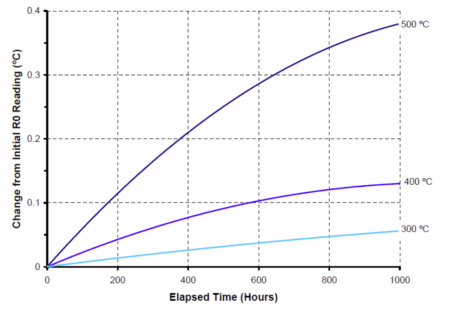
Figure 1. Typical change in ice point reading versus time at temperature, for an industrial grade RTD
The probe ice point reading will change not more than ±0.13ºC for 1000 hours at the maximum rated temperature
- Drift Due to Temperature Cycling. When a probe is exercised between temperature extremes the platinum sensing element can become stressed due to the expansion and contraction of the different materials used in the construction of the probe. The affect on accuracy is more detrimental when the temperatures are more extreme and the rate of temperature change is greater. A graph similar to the example in figure2 may be available for a particular RTD. At a minimum, a single defining point should be provided. For example:

Figure 2. Typical change in ice point reading versus number of cycles between temperatures
The probe ice point reading will change not more than ±0.13ºC after 10 cycles between the maximum and minimum rated temperatures.
- Vibration. In many applications RTDs have to withstand the constant vibration of the equipment or process that it is monitoring. If the vibration is extreme enough it can cause stress in the platinum sensing element which can result in erosion of accuracy. RTD manufacturers typically state a vibration test schedule that a probe can withstand without a significant change in accuracy. A typical specification might be:
Less than ±0.075 ºC ice point shift after 30 minutes at 21g peak vibration 5-350 Hz continuous sweep, at 20 ºC for unsupported lengths of 5.5” or less.
The next three specifications benchmark the probes initial performance. If the initial performance is known it can be used to determine the deterioration of the probe at subsequent verifications.
- Initial Ice Point Resistance. The actual initial resistance at the ice point (R0) should be obtained from the manufacturer. If the actual ice point resistance is not provided, the manufacturer should be able to provide a nominal value with an interchangeability tolerance (e.g. 100Ω ± 0.10Ω).
- Time Response. Time response measures the RTD’s ability to match a step increase in temperature. A typical industrial probes time response is stated as:
4 seconds for a 63.2% response to water moving at 3 fps.
However it may be more useful to benchmark the initial time response of the probe in the application.
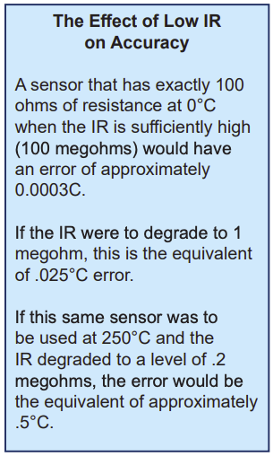
- Insulation Resistance. Insulation resistance (IR) is the resistance between the electrical circuit containing the sensing element and its outside environment. Very often the IR of the probe can be measured with the probe installed in its application. IR acts as a shunt resistor to the measurement circuit; the lower the IR the higher the effect on the accuracy of the probe. The manufacturer should be able to provide a threshold value for initial IR. A typical statement of IR is:
Greater than 500 MΩ measured at 500 VDC when the probe is at 20ºC
The user should also be aware that at elevated temperature IR will be significantly lower than the room temperature value. If an elevated temperature IR value is provided, this value could be important to the analysis for sensors used at elevated temperatures within their prescribed operating range. Table 1 shows the specifications as defined by ASTM E1137. You may note that these values are stated as minimums. Most RTD manufacturers strive for much higher initial IR performance.
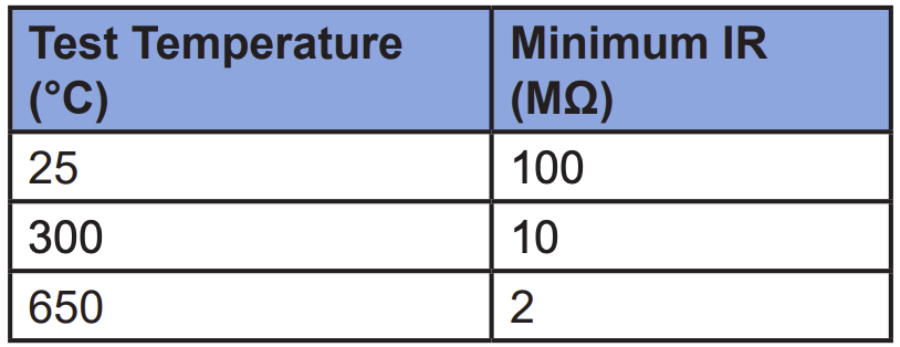
Table 1. ASTM E1137 RTD Insulation Resistance Requirements
OPERATING ENVIRONMENT
The next step is to evaluate the environment the RTD is being used in against the specification.
- Temperature Cycles. It is important to understand the nominal temperature the probe will experience and the time held at that temperature. In addition it is important to know how often the probe will see excursions to extreme temperatures.
- Vibration. How much vibration the probe experiences when it is installed is often difficult to calculate but an assessment of the severity should be made. High vibration environments should be a red flag that results in a relatively short initial verification period.
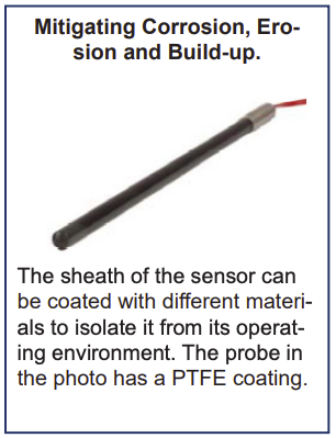
- Corrosion, Erosion and Build-up. Some processes can cause the sheath/thermowell to erode or corrode away; other process may cause a substance build up on the sheath. A thermowell can protect the probe from its operating environment but even when a thermowell is used corrosion, erosion and build-up can still negatively effect the operation of the probe so adequate limits need to be set. Corrosion and erosion will, if left unchecked eventually breach the probe’s protective housing and render the probe inoperable. Build-up will reduce the time response of the sensor and increase the self heating. The self heating, caused by the measuring current passing through the resistance platinum element, can affect the accuracy of the temperature measurement. Installations with sufficient thermal contact with the process, the self-heating effect is generally negligible, but when build up insulates the probe it can become significant.
- Infrequent Events. These include planned events such as wash down cleaning or unplanned events such as instrumentation voltage spikes that can very quickly negatively affect the accuracy of the probe.
INITIAL VERIFICATION PERIOD
Armed with a clear understanding of the probe performance and the operating environment the initial verification period can be established. First decide on the maximum deviation from actual temperature the measurement can tolerate. This could be based on energy costs, temperature of material spoilage etc. Once the maximum deviation is known a predication as to the time when the probe might fall outside the acceptable accuracy limits can be made by using the probes published accuracy deterioration rates that were discussed earlier.
Outside of temperature, when applicable, if build-up or corrosion/erosion rates are known then an estimate as to the time in service when these might start to be a concern can be determined. If this yields a verification time that is shorter than the drift due to temperature then this criteria should be used to set the initial verification period.
In addition to the time based approach consideration should be given to an event based approach even if only an abridged verification takes place. For example in a wash down situation it might be prudent that after each time the wash down is performed the probes IR is measured and compared to the established benchmark.

VERIFICATION TECHNIQUES
Before any verification of the accuracy the RTD, an IR measurement should be taken and confirmed that it is still within the manufacturer’s threshold value.
Taking an R0 reading is the most efficient way to determine the accuracy of the probe. Fortunately it is a relatively easy and low cost task to create an ice/water bath that provides a sufficiently accurate 0ºC temperature point. By monitoring the R0 value of the probe over subsequent verification intervals it is possible to build up a history that can be used to predict the future performance of the probe. Within the resistance versus temperature curve that fully characterizes the probe the R0 point is commonly used as a confirmation that the probe is consistent over time. If there is any doubt about the probes performance at other temperatures, or if the typical operating temperature is of most concern, then it should be tested at, or close to, those temperatures.
In the case of erosion/corrosion being a concern then the outside diameter of the probe should be closely measured and monitored. If build-up is a concern then some type of time response measurement should be tracked. This may be able to be done with sufficient accuracy using the process the probe is measuring or it may be necessary to rely on industry standard techniques such as those detailed in ASTM E644-09 Standard Test Methods for Testing Industrial Resistance Thermometers. A separate inspection/cleaning schedule could be established to manage this affect. This schedule could match the performance verification timing or timed with other system maintenance due to the need to open the process barrier.
OPTIMIZING THE VERIFICATION PERIOD
As discussed earlier the initial verification period is set using the RTD manufacturer’s specifications and the user’s knowledge of the probes operating environment. After a number of verifications are complete the user should have enough R0 data to predict actual accuracy deterioration rates. These calculated rates are much more appropriate for the user’s particular application than those provided by the RTD manufacturers and should be used to optimize the verification period.