
Your Temperature Measurement Experts
Error Sources That Effect Platinum Resistance Thermometer Accuracy Part 5: Hysteresis
There are many sources of error that affect the performance of Platinum Resistance Thermometers (PRTs). These error sources are inherent in the design and manufacture of all PRTs, but the magnitude of the resulting error in use can vary greatly depending on the specific PRT design and environment that it is used in. It is important for users of PRTs to know and understand what these error sources are so they can make intelligent decisions related to PRT selection and use. The most common error sources fall within the following categories: Interchangeability, Insulation Resistance, Stability, Repeatability, Stem Conduction, Hysteresis, Calibration and Interpolation, Lead Wire Resistance, Self-Heating, Time Response, and Thermal EMF. This paper will discuss the topic of Hysteresis.
Hysteresis
In general, hysteresis is a phenomena that results in a difference in an items behavior when approached from a different path. In PRTs, thermal hysteresis results in a difference in resistance at a given temperature based on the thermal history to which the PRT was exposed. More specifically, the resistance of the PRT will be different when the temperature is approached from an increasing direction vs a decreasing direction, and the magnitude of the difference will depend on the magnitude of the temperature excursion and the design of the PRT.
Industrial specification IEC 60751 refers to this as “Effect of hysteresis” and states that the PRT resistance shall be measured at the middle temperature after exposure to the lower limit temperature and after exposure to the upper limit temperature. The acceptance criteria that is given is that the resistance at the mid point cannot change by more than the tolerance value at the test temperature for the respective tolerance class tested. It does not state that both measurements must meet the resistance tolerance, therefore it is possible that the hysteresis effect could result in the sensor producing an out of tolerance measurement. ASTM standard E1137 does not contain any requirement for thermal hysteresis however, a test method for hysteresis testing is contained in ASTM standard E644 which would allow testing over ranges less than the maximum rated range of the PRT. While the requirement of the IEC 60751 standard is fairly well defined, it does not provide any information about hysteresis when the range is less than the maximum, and neither of these industrial PRT standards provides information about the hysteresis performance at temperatures other than the mid point temperature where hysteresis is considered to be at its maximum.The information that would be valuable for a good understanding of a PRTs hysteresis would be if the hysteresis was specified as a percent of span to which the PRT was exposed.
The graph in Figure 5-1 below shows a hypothetical representation of what could be considered a very well behaved hysteresis loop on a typical industrial PRT. The hysteresis is a maximum at the mid point temperature and a minimum at each end point. While there is still some variability expected in the measurements taken at the end points, this variability is caused by the PRT repeatability, not by hysteresis.

Figure 5-1
Hypothetical Well-Behaved Hysteresis Loop for Industrial PRT
One simplified method to estimate the hysteresis error at any temperature within the range of use is to perform a linear interpolation between the mid point temperature and the temperature of interest. Since no known equation exists for this estimate, one was created, for the purpose of this paper we will call it the Zwak-Zenner equation and it is given as:
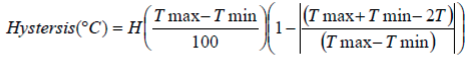
Eq. 1
Where:
- H = hysteresis error coefficient in % of temperature span
- Tmax = Maximum temperature of span
- Tmin = Minimum temperature of span
- T = Temperature where hysteresis is being determined
To get a feel for the order of magnitude for the hysteresis error, several examples were created. Table 5-1 below shows the estimated hysteresis error in °C calculated using this method for PRTs with varying specifications over several common temperature ranges.

Table 5-1
Hysteresis Error Estimates for Common Temperature Ranges
By examining the values in Table 5-1 it is easy to see that the hysteresis error can be nearly negligible, or may be approaching as much as ±1°C.
Causes of Hysteresis Error
The most prominent factor that contributes to the hysteresis error in a PRT is strain within the sensing element caused by thermal expansion and contraction. Most industrial grade PRTs are manufactured using a sensing element made from a fine diameter platinum wire, typically less than .001 inch diameter, or a thin film platinum element. The other materials used to manufacture these elements are critical because they are in direct contact with the fragile platinum and must provide mechanical support and protection while still allowing for free thermal expansion and contraction over a wide temperature range. These elements are then packaged into the final sensor configuration, where the materials used must also allow for free thermal expansion and contraction or additional strain can occur.
The strains that cause hysteresis error are closely related to the strains that cause repeatability error. Therefore, it is typical that PRTs that exhibit small hysteresis also exhibit small repeatability, and PRTs that exhibit large hysteresis exhibit large repeatability. It is worth noting that Standard Platinum Resistance Thermometers (SPRTs) are required to have their platinum element coils be strain free to prevent thermal hysteresis error, resulting in an extremely accurate sensor. To accomplish this, the SPRT element resistance wire is not well supported and that makes these instruments very delicate and virtually unsuitable for use anywhere except in a laboratory. Conversely, very rugged industrial PRTs that are designed for high vibration use may need to have their wires thoroughly supported resulting in a less accurate but highly rugged sensor.
How to Reduce Hysteresis Error
Hysteresis is controlled almost exclusively by the design and manufacture of the PRT and the temperature span to which the PRT is exposed. The best way to reduce hysteresis error is to select a PRT that has a low specified hysteresis and minimize the temperature span to which the PRT is exposed. Keep in mind that hysteresis is a maximum at the midpoint temperature and is zero at the end points, so using a sensor near the end points can reduce the magnitude of this error.
If actual calibration data is to be used for minimizing Interchangeability or other error sources, and the PRT hysteresis error is unknown or is known to be significant for the application, it may be worth measuring the middle calibration temperature(s) after maximum and minimum exposures, and averaging the two readings to determine the average R vs T relationship. This would provide a R vs T relationship that is centered within the hysteresis loop rather than a relationship that is based on only increasing or decreasing temperature exposures.
Summary
There are many sources of error that affect the performance of a PRT. One of these sources is Hysteresis, the ability of a PRT to maintain its R vs. T relationship when approaching a temperature from an increasing or decreasing direction. The cause of hysteresis is strain in the sensing element caused by thermal expansion and contraction. The best way to reduce hysteresis error is to select a PRT that has a low specified hysteresis, and not to expose the PRT to a temperature span larger than necessary. If calibration data is to be used and the hysteresis error may be significant for the application, it is advisable to take the middle calibration point(s) after maximum and minimum temperature exposure and average them.