
As the length increases and/or the diameter decreases the resistance of the conductor increases. To maintain flexibility, cables are usually manufactured from multiple drawn strands of thin wire that are twisted together to form a conductor of the correct diameter for the particular wire gauge size. The bare twisted strand conductor is then insulated. Several insulated conductors are twisted together to form the cable, then an insulating and protective jacket is applied over the twisted conductors.
Each one of these steps involves de-reeling the wire, passing it through a series of tensioning pulleys through the process and then spooling it back onto another reel before it goes onto the next step. This processing of the wire, despite the best efforts of the cable manufacturers, causes the conductors to stretch. The stretching of the cable results in a reduction in cross sectional area and thus an increase in cable resistance. From lot to lot it is difficult to consistently control the stretching. Typically the conductors that make up the cable come from different production runs. Ultimately when the different conductors are brought together to form the cable they have slightly different cross-sectional-areas, although still within the standard for the gauge size, but resulting in an imbalance in their resistances.
In the case of copper conductors, the copper is typically plated with silver or nickel to improve the corrosion resistance. The overall resistance of the conductor is a function of the resistivity of the two materials and their corresponding cross sectional areas. Unfortunately thickness control in the plating process is difficult. Any variation in the thickness results in a variation in the cross-sectional area. When the resistivity of the plating material is high this problem is exacerbated.
Nickel is a common plating material used for copper conductors and has a resistivity much higher than the copper. So a variation in thickness of the nickel results in a larger variation in the resistivity of the conductor.
Another common plating material for copper is silver, which has a lower resistivity than nickel. Any variation in the thickness of the coating of the silver has much less of an effect on the conductor resistivity compared to what a similar variation in nickel plating would have. However there are cost, corrosion and temperature constraints that have to be considered when selecting silver rather than nickel.
Magnitude of the Imbalance in the Cable
For applications where circuit resistance is not important to the function, the imbalance in the conductors of the cable is not significant enough to cause a problem. Basically the ASTM standards only specify the cross-sectional area of the conductor and the plating thickness. The variation allowed in the Standards, yields a range in wire resistance greater than the three wire RTD compensation method can accept. Most cable manufacturers are able to do much better than what the ASTM standards dictate. One cable manufacturer we have consulted with states that a maximum variation of 4% in resistivity for silver plated wire and 11% for nickel plated wire is considered achievable.
To highlight the issue, consider the example of a Class A temperature sensor built with 30 feet of 30 AWG nickel plated copper cable.
- A 30 AWG conductor has a resistivity of 99.2 Ω/1000ft, so for a 30’ sensor cable the resistance of each conductor will be 2.976 Ω. Assuming the 11% achievable matching value, the variation between conductors could be as much as 0.327 Ω.
- A “class A” sensor at the ice point (0.0 ºC) has a resistance of 100 ±0.060 Ω. Typically a “class A” sensor will be built utilizing an element with an initial ice point resistance tighter than the Class A tolerance to allow for slight variation due to the manufacturing process. Clearly there is no room in the tolerance budget to support the potential imbalance of 0.327 Ω. In terms of temperature, the tolerance at the ice point for a Class A sensor is; 0.0 ± 0.156 ºC. The imbalance in the cable conductors (0.327 Ω) will cause an additional error of approximately 0.85ºC effectively resulting in a three wire sensor with an ice point accuracy 6 time larger than the design target, or approximately 0.0 ± 1°C.
Methods to Mitigate the Errors from Cable Imbalance
Steps can be taken to mitigate the problem of cable imbalance in a three wire temperature sensor. The list below gives an overview of each of the options. Typically some compromise needs to be made in order to reduce the effect of cable imbalance.
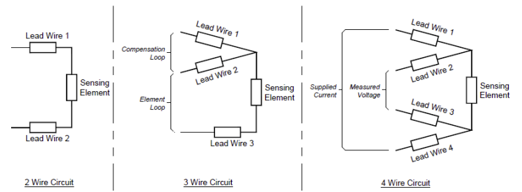
- Switch from a three wire sensor to a true four wire sensor. A true four wire measurement negates any effect of lead wire resistance and thus will always give a superior measurement. It is not always possible to switch to a four wire configuration, sometimes due to space constraints in the probe or because the existing control or meter infrastructure is configured for three wire sensors.
- Increase the cable gauge. For a three wire measurement the cable conductor gauge used should be as large as possible. As seen earlier the larger the cable gauge the lower the resistance and the lower the imbalance in the conductors in the cable. Space constraints inside the RTD often do not allow for a larger cable size. Even with a larger cable there will be a cable length at which the possible cable resistance imbalance will result in the sensor being out of its accuracy tolerance.
- Splice to a larger cable outside the RTD. If space constraints internal to the RTD prevent incorporating a larger cable size then a larger cable can be spliced to the small cable outside of the sensor. In the area of the splice the cable will be stiffer and will have a slightly larger diameter than either of the cables. This may make it difficult to pass the cable through conduit. Again even with a larger cable gauge in the circuit there is still a cable length at which the possible cable resistance imbalance will result in the sensor being out of its accuracy tolerance.
- Resistance Trim the cable and fix the length. The cable can be balanced by adding a compensation resistance to the appropriate conductor(s) in the cable. Typically, the compensation resistance is added near the end of the cable to keep it away from process temperatures. To maintain the accuracy of the temperature sensor it is important that the cable is not cut during installation as this will physically remove the compensation resistance and return the cable to its original unbalanced state.
- Switch to a silver plated copper cable. By switching from a nickel plated copper to a silver plated copper cable will allow for longer cable lengths. Silver has a lower temperature rating and does not do particularly well in moist environments.
Conclusion
A high accuracy temperature measurement requires a true four wire sensor. When the application will not allow for a four wire sensor a three wire sensor can be utilized but the end user should be aware of how the accuracy is potentially being affected by the three wire circuitry. Some probe manufacturers do not address the issue of degradation of measurement accuracy with reduced cable gauges and/or longer cable lengths; however the cable imbalance issue is always present. By taking into consideration the effects of cable imbalance at the time a three wire sensor is specified, and by carefully evaluating and selecting one of the techniques to reduce the effect of cable resistance imbalance, it is possible to produce a three wire measurement probe that will provide a temperature measurement at the needed accuracy.